Let’s dive into some more detail about what exactly this project entails.
To make a proper hardware-in-the-loop testbench, henceforth called a HITL, you’ll need to simulate two parts to be as close to the car as possible:
- The electromechanical components
- The sensor inputs and software
All of those come together into the following system overview:
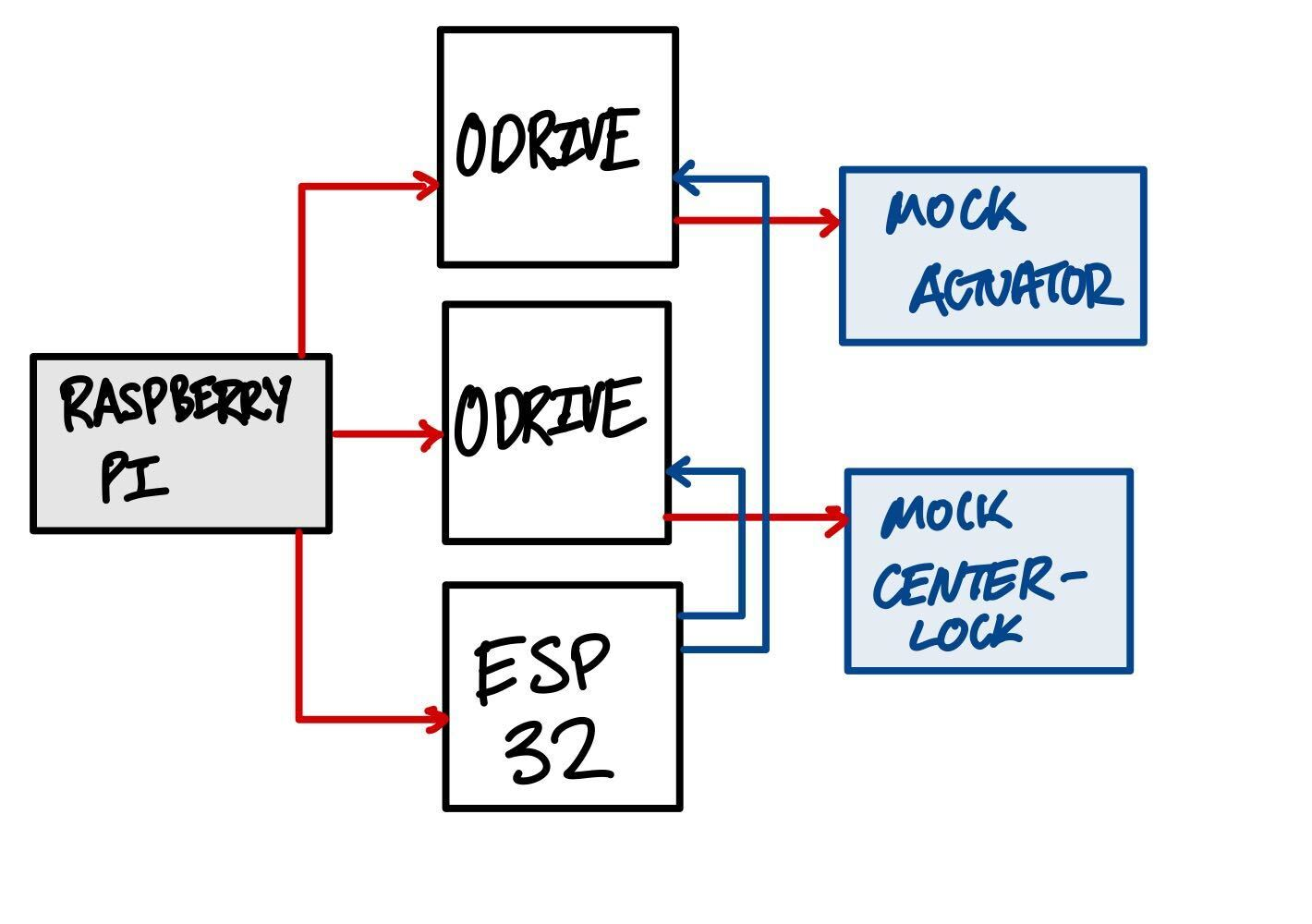
In this system diagram, the Raspberry Pi will be the main brains of the operation, controlling the ESP32, and O-Drives (our motor controllers, I’ll teach you about this in a future lesson).
The ESP32 and the O-Drives are the main bulk of our system electrically. We’ll be using the Raspberry Pi to command them, and validate that they’re working properly. We’ll also be using the Raspberry Pi to simulate sensors on the car, without having to actually implement them.
On the hardware side, we’ll be making modified versions of our electromechanical actuator for the automatic transmission and we’ll be making a modified version of our 2WD→4WD center-lock clutch.
We’ll be using the same hardware as on the car, but with a different form factor. This will allow us to test how our software integrates and interacts with the two most important electromechanical systems on the car, before the car is finished being built!
Software Scope of Work
- Create a library to interface with the O-Drives from the Raspberry Pi, using the Python command line interface odrivetool.
- Create a library to simulate sensors on the car using the Raspberry Pi.
- Create a library to fetch data from the ESP32, using our in-house telemetry system.
- Design hardware tests with sufficient coverage to verify that code works!
Hardware Scope of Work
- Design and test the mock versions of the center-lock and the ECVT actuator.
- Package all mechanical and electrical components into a single drawer in the electronics cabinet.
- Make the setup portable and easy to use at competition.